Connecting a DEC Consolette to a Black & Gray Box Jukebox
Since Seeburg designed the Black & Gray box system around the remote-selection Consolette idea, it was naturally pretty straightforward to connect a DEC to one of these jukeboxes. Both the DEC and the SC, SCH Consolettes it replaced use a 10-wire cable for interconnect. The older 3W1 series used only three wires. For the DEC, a minimum of six wires (two power, and four data) are needed to make a selection. Three more will get you audio, and another will get you audio control (home installations probably don't need this), for a total of ten. For locations still having the SC or SCH Consolette, Seeburg offered the Seeburg Remote Translator or SRT1, which would translate the pulses output by those older Consolettes into the format required for the newer jukebox.The diagram below shows the wiring specifics of connecting a DEC to your jukebox, and shows the most basic connections to the console.

TB3600 is the 10-position terminal strip located inside the DEC. A similar terminal strip should be mounted inside the rear portion of the console, close to the mechanism access hatch and cabling knock-outs, but out of the way of the mechanism carriage. The cable wire colors shown are what Seeburg provided in their cable, but are obviously arbitrary, as long as you observe the correct connections. For the two power wires (24 VAC and Ground, shown as heavy lines) use at least AWG (American Wire Gauge) 18 gauge Stranded wire. Note that as the wire diameter increases, the gauge number decreases. For the remaining wires, AWG 20 or 22 should suffice. Due to power supply requirements, you should connect a maximum of six Consolettes to any single cable. If you have more to connect, use an additional cable and power supply for each six connected.
Power Supply
Seeburg offered the accessory Digital Consolette Power Supply or DCPS1-56 (for 120 VAC 50-60 Hz supplies) or the DCPS1-H5 (for 220 VAC 50 Hz Mains). This supply outputs 24 VAC at a maximum of 3 Amps, which is sufficient to supply six Consolettes, each requiring about 0.5 Amp. If your console does not have the optional Dollar Bill Validator (DBV), you can use the validator DCC jack (J3108) to power your Consolettes instead of the DCPS1, as long as you insure that the Consolette cable ground wire is connected to pin 1 of J3108. DO NOT connect a DCPS1 AND the DBV jack to the same cable, or two DCPS1s to the same cable. For safety's sake, you should connect a wire between the Ground terminal of the 10-position terminal strip and a metal jukebox panel which is in turn connected to the ground wire of the three wire power cord for the jukebox. Do not use 'cheater' plugs. Make sure you have a good ground connection.
Data Lines
Wires Line A, B, C, and D are the four selection and coin data lines. Selections are made by rapidly pulsing one or two of the four lines to a negative voltage, three times for each selection. The first set of pulses are the hundreds digit of the selection, while the second and third sets define the tens and units digits, respectively. Coin information is transmitted by pulsing one of the lines to a positive voltage, as determined by the value of the coin. This information is recorded by the optional Recording Income Totalizer for record-keeping purposes.
Audio Wires
Audio is delivered to the DEC using three wires, Audio Left, Audio Right and Audio Gnd. These connect to the DEC speakers through an internal audio control relay, K3600, and the soft/loud buttons on the DEC front panel. The relay is energized whenever a selection is made from the Consolette, and de-energized the second time the mechanism carriage reaches the 179/279 end of the magazine after the last DEC selection was made. The Audio Control wire conveys this 'audio off' information to the Consolettes. If you have a home installation and want to keep audio on all the time, solder jumpers across the K3600 relay contacts or simply don't use the Audio Control wire. The first selection made after powering up the jukebox will turn the audio on, and it will stay on until you turn the jukebox off. Then you don't need the Audio Control wire, so the cable only needs nine wires. If the amplifier is wired the way it left the factory, the Consolette Speaker connections use the amplifier 4 Watt audio taps. Depending on the number of Consolettes you have connected, you might want to move these wires (yellow, left, and green, right) to a higher wattage tap.
Console Connections
The connections within the console itself should be made using the Seeburg accessory Consolette cable (Seeburg used Belden #8784 cable as its Consolette cable) or similar to connect the console to the DEC(s). Inside the machine, strip off the cable jacket and use plastic tie wraps every five or six inches to keep the wires routed together and away from moving parts. Depending upon which jukebox you have, it should be easier to make the data line and audio connections to the SN12 or AJU, mounted in the vicinity of the mechanism access hatch and cable knock-outs at the rear of the jukebox. The table below details the connections as a function of jukebox model.
| Model Name (Year) | Data Connections | Audio Connections | Comments |
| LS3 Apollo (1969) | DCC J3105 (white 6 contact housing) | Amplifer TSA8/10 TB5102 | This machine had no special DEC cabling installed |
| USC1 Bandshell (1970) | Accessory Junction Unit (AJU) white 6 contact housing | AJU 3-lug audio terminal board | Should be located to the right of the mechanism, as viewed from the front |
| USC2 Firestar (1971) | AJU (see USC1) | see USC1 | See USC1 |
| SPS160 Olympian (1972) | SN12 Stereo Network (white 6-contact housing) | SN12 3-lug audio terminal board | Mounted just above mechanism access hatch |
| FC1 Regency (1972) | DCC J3105 (white 6-contact housing) | Amplifier SHP3 TB5102 | This machine had no special DEC cabling installed |
| SPS2 Matador (1973) | SN12 (see SPS160) | SN12 (see SPS160) | See SPS160 |
| STD160/SQS160 Vogue II (1974) | SN12 (see SPS160) | SN12 (see SPS160) | See SPS160 |
| STD2/SQS2 Entertainer (1975) | SN12 (see SPS160) | SN12 (see SPS160) | See SPS160 |
| STD3/SQS3 Sunstar (1976) | SN12 (see SPS160) | SN12 (see SPS160) | See SPS160 |
| FC2 Hutch (1976) | DCC J3105 (see FC1) | See FC1 | See FC1 |
| STD4 Mardi Gras (1977) | SN12 (see SPS160) | SN12 (see SPS160) | See SPS160 |
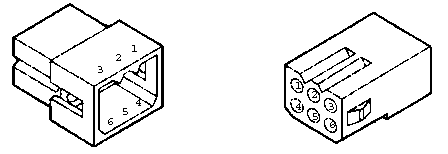
Suitable pins and housings to mate with the jukebox connectors can be obtained from any local electronic supply store. Generally speaking, your local Radio Shack does not stock the correct components. The connectors and pins are manufactured by Molex, Inc. The Data connections use the Molex .062 Std series 6-contact male housing (Molex 03-06-2061) and male terminal (02-06-2103). The DCC DBV connector is from a different series. The pinout of the six-contact housing is below.
![]()
![]()
![]()
![]()
![]()
![]()
![]()
![]()